.png)
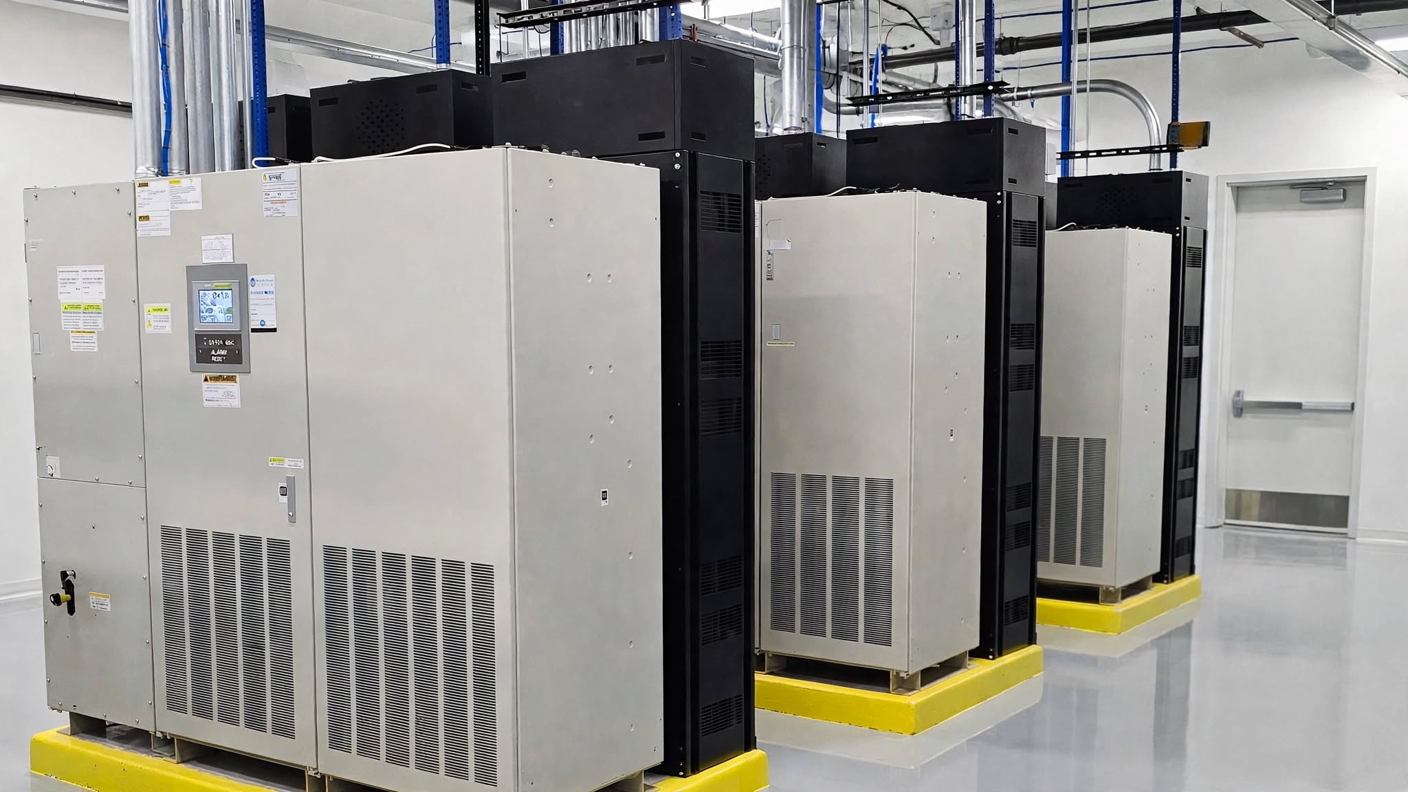
Emergency Power Off (EPO) is an important safety function in facilities that use Uninterruptible Power Supply (UPS) systems to protect critical electrical loads. While a UPS is designed to maintain power during electrical disturbances and outages, an EPO system provides a controlled method to rapidly disconnect power from equipment during a serious emergency.
A properly engineered EPO system can help personnel respond quickly to events such as electrical fires, smoke, flooding, equipment failures, or other conditions where maintaining energized equipment could increase the risk to people or property.
Why Is EPO Needed for a UPS System?
A UPS is designed to keep critical equipment energized. That is its primary purpose—but during an emergency, maintaining power may become a safety concern.
For example, consider an electrical room where a major equipment fault or fire occurs. Under normal circumstances, the UPS may continue supplying the load from its battery or another available power path. If emergency responders need the equipment de-energized, simply opening the normal utility source may not be sufficient, because the UPS can continue providing output power from its stored energy.
This is one of the most important reasons for an EPO system.
EPO provides an emergency means of initiating a rapid shutdown or disconnection of the UPS and associated electrical equipment, depending on the system design.
EPO can be particularly important when:
· An electrical fire or severe equipment fault occurs
· Emergency personnel need equipment de-energized
· Smoke or overheating is detected
· Water intrusion creates an electrical hazard
· Maintenance personnel face an immediate electrical safety risk
· A critical equipment failure requires emergency isolation
· Local electrical and fire-safety requirements call for an emergency shutdown function
The exact equipment that an EPO operates should always be determined during the engineering and safety design process
How Does UPS EPO Work?
An EPO system typically consists of an emergency stop device, control circuit, and interface with the UPS and/or upstream and downstream electrical equipment.
The EPO device is commonly installed at a location that is:
· Clearly visible
· Easily accessible
· Properly identified
· Located where emergency personnel can reach it quickly
When the EPO is activated, its signal can initiate predefined actions such as:
EPO activation → UPS shutdown/control action → input/output switching action → removal of power from designated equipment
However, the exact sequence varies significantly between UPS manufacturers and system architectures.
For example, an EPO may:
· Shut down the UPS inverter
· Open the UPS input circuit
· Open the UPS output circuit
· Disconnect battery energy
· Operate external contactors
· Initiate a facility-wide emergency shutdown
· Interface with switchgear, ATS, STS, or other power equipment
Therefore, EPO should never be treated as simply a large “OFF” button. It is a safety-critical control function that must be coordinated with the complete electrical system.
EPO and UPS Battery Power
One of the most important considerations is the UPS battery.
A common misconception is:
“If the utility power is disconnected, the UPS output is automatically dead.”
That is not necessarily true.
If the UPS is operating on battery, it can continue supplying its output even after the incoming utility source has been disconnected.
This is precisely why the EPO design needs to consider all possible sources of energy.
A typical UPS installation may have:
Utility → Switchgear → UPS → Distribution → Critical Load
But the UPS may also have:
Battery → UPS DC Bus → Inverter → Critical Load
Therefore, simply disconnecting the utility does not necessarily eliminate the UPS's stored-energy source.
A properly engineered emergency shutdown strategy must address the applicable energy paths and clearly define what equipment becomes de-energized when EPO is activated.
EPO in Data Centers
Data centers are one of the most important applications for UPS EPO systems.
Modern data centers may contain:
· Multiple UPS systems
· Battery cabinets
· Static Transfer Switches (STS)
· Automatic Transfer Switches (ATS)
· Switchgear
· PDUs
· Server racks
· Cooling systems
· Generators
· Multiple electrical distribution paths
Because of this complexity, an EPO system must be carefully coordinated.
For example, a facility could have:
UPS A → PDU A → Critical Loads
and
UPS B → PDU B → Critical Loads
If the EPO system is designed incorrectly, activating one emergency device could potentially affect both power paths.
This can create a significant operational and availability risk.
EPO design should therefore clearly establish:
· Which UPS systems are affected
· Which loads are disconnected
· Whether battery systems are isolated
· Whether upstream breakers operate
· Whether downstream distribution is affected
· Whether generators are affected
· Whether cooling systems remain operational
· Whether STS equipment is affected
· Whether multiple EPO zones exist
For high-availability facilities, selective EPO zoning can be an important design consideration.
EPO vs. Normal UPS Shutdown
EPO should not be confused with a normal UPS shutdown.
Function Normal UPS Shutdown Emergency Power Off
Primary purpose Controlled equipment shutdown Emergency safety response
Normal operation Yes No
Controlled sequence Typically, Depends on design
Emergency use No Yes
Can disconnect critical power Typically, not immediately Potentially
Safety function Limited High
Activation Operator/control system Emergency device
A normal UPS shutdown is generally performed as part of planned operation, maintenance, or equipment management.
EPO is intended for emergency conditions.
EPO Design Considerations
A reliable EPO system begins with a clear understanding of the facility's electrical architecture.
1. Identify Every Energy Source
Engineers should identify all sources capable of energizing the equipment.
These may include:
· Utility power
· Generator power
· UPS input
· UPS bypass
· UPS battery
· Alternate UPS systems
· Backfeed sources
· Energy-storage systems
The EPO strategy should account for the relevant sources rather than assuming that one breaker disconnects everything.
2. Define the EPO Zone
One of the most important design questions is:
What exactly should turn off when EPO is activated?
The answer should be clearly documented.
Depending on the facility, the EPO zone may include:
· One UPS
· Multiple UPS systems
· One electrical room
· A complete data hall
· Specific distribution equipment
· Selected critical loads
3. Consider Redundant UPS Architectures
Redundant UPS systems require special attention.
For example:
UPS A → STS → Load
UPS B → STS → Load
If both UPS systems support critical loads, the EPO design must clearly define whether one EPO action affects:
· UPS A only
· UPS B only
· Both UPS systems
· Both STS systems
· The complete critical-load distribution
A poorly coordinated EPO system can unintentionally create a single point of failure in an otherwise redundant electrical architecture.
EPO Pushbutton Location
The EPO actuator should be positioned so that authorized personnel and emergency responders can identify and operate it quickly.
Important considerations include:
· Clear labeling
· Accessibility
· Visibility
· Protection against accidental operation
· Appropriate mounting height
· Coordination with fire and life-safety systems
· Proper identification of the equipment controlled
Because accidental EPO activation can cause an immediate loss of critical power, the design should also consider protection against inadvertent operation while maintaining emergency accessibility.
EPO and Fire Alarm Systems
EPO systems may also interact with a facility's fire alarm or emergency management system.
However, this integration should not be assumed to be automatic or universally required.
The engineering team should determine:
· Whether the fire alarm system should initiate EPO
· Whether EPO should initiate another emergency signal
· Which equipment should remain energized
· Whether HVAC or smoke-control systems require separate treatment
· How the emergency sequence interacts with generators and other power sources
The final sequence should be coordinated among the electrical engineer, fire-protection engineer, UPS manufacturer, facility operator, and applicable authorities having jurisdiction (AHJ).
EPO Testing and Maintenance
Installing an EPO system is only part of the process.
The system should be tested, documented, and maintained so facility personnel understand exactly what happens when the EPO is activated.
Testing should verify, as applicable:
· EPO device operation
· Control circuit continuity
· UPS response
· Breaker operation
· Battery isolation response
· Bypass behavior
· Generator interaction
· STS response
· Alarm indications
· Building-management-system signals
· Restoration procedures
Testing must be performed using an approved procedure because an EPO test on a live critical facility can create a serious service interruption.
The Importance of EPO Documentation
A well-designed EPO system should be supported by clear documentation.
Important documents include:
· Single-line diagrams
· EPO control schematics
· Sequence-of-operation documents
· Equipment schedules
· UPS manuals
· Battery documentation
· Breaker/control diagrams
· Testing procedures
· Emergency operating procedures
The Single-Line Diagram (SLD) should clearly show the relationship between the EPO system and the electrical equipment it controls.
This is especially important for facilities with multiple UPS systems, redundant distribution paths, generators, ATSs, and STSs.
Common EPO Design Mistakes
Several mistakes can reduce the effectiveness of an EPO system.
1. Treating EPO as a simple UPS ON/OFF switch
EPO is a safety function—not simply a convenient way to shut down a UPS.
2. Ignoring stored battery energy
Disconnecting the utility does not necessarily eliminate UPS output power.
3. Not considering bypass sources
A UPS may have a maintenance bypass or static bypass path that remains energized depending on the configuration.
4. Poor coordination with redundant systems
An EPO command affecting multiple redundant power paths can unintentionally remove the facility's entire critical power supply.
5. Inadequate labeling
Emergency personnel need to understand exactly what an EPO device controls.
6. Failure to test the complete sequence
An EPO system should not be considered reliable simply because the pushbutton illuminates or the control circuit shows continuity.
EPO Is a Safety System—Not a Convenience Feature
The fundamental purpose of EPO is to provide rapid emergency control of electrical energy when continuing to energize equipment could create an unacceptable safety hazard.
At the same time, EPO introduces an important engineering trade-off:
Safety vs. availability.
For a mission-critical facility, an incorrectly designed EPO system can cause unnecessary loss of power to critical loads. Conversely, an inadequately designed emergency shutdown system may fail to remove the intended energy sources during an emergency.
The objective is therefore not simply to install an EPO button.
The objective is to design an engineered emergency power-off strategy that is safe, clearly defined, coordinated, tested, and appropriate for the facility's electrical architecture.
Hatch Power: UPS and Power Quality Expertise
Hatch Power provides UPS consulting, UPS system design, maintenance, power-quality assessment, harmonic analysis, and UPS technical services for commercial and industrial applications.
For facilities considering a new UPS installation, upgrading an existing UPS, or evaluating an EPO strategy, a professional engineering review can help identify energy sources, bypass paths, redundancy implications, control interfaces, and potential single points of failure before the system is commissioned.
Conclusion
UPS Emergency Power Off (EPO) is a critical safety function for facilities where UPS systems can continue supplying electrical energy during an emergency.
The key point is simple:
A UPS is designed to keep power ON. An EPO system is designed to provide a controlled means of turning designated power OFF when an emergency requires it.
Effective EPO design requires more than installing an emergency pushbutton. It requires a complete understanding of the UPS topology, battery system, bypass sources, switchgear, STS/ATS equipment, distribution architecture, emergency procedures, and applicable safety requirements.
When properly engineered and tested, an EPO system can provide an important layer of protection for personnel, equipment, and critical facilities—without unnecessarily compromising the reliability of a properly designed UPS architecture.