
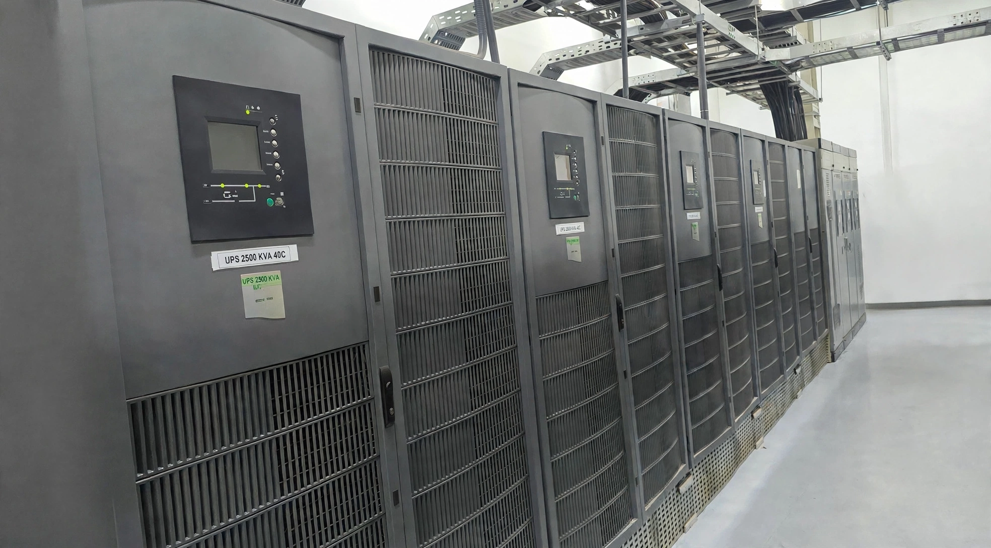
Parallel UPS systems are powerful—but they’re also where most catastrophic failures happen if design, controls, or commissioning are even slightly off. Below is a field-proven breakdown of the real failure modes, not brochure theory.
1- Load Sharing Failure (Most Common)
What happens
One UPS in the parallel set:
· Takes more than its share of kW or kVA
· Heats up faster
· Hits current limit or overload first
The rest follow → cascade failure
Root causes
· Output impedance mismatch
· Bad current transformers (CT polarity / ratio)
· Poor paralleling control tuning
· Mixed UPS models / firmware
· Unequal cable lengths
· Calibration issue
Symptoms
· For example: One UPS at 95% while others at 70%
· Random overload alarms
· Sudden system switch off inverter
2- Control / Communication Failure
Parallel systems depend on communication.
Failure modes
· Paralleling bus failure (CAN, RS-485, fiber, Ethernet)
· Master/slave election failure
· Sync loss between modules
What happens
· UPSs no longer agree on:
o Voltage reference
o Phase angle
o Frequency
Result:
· Circulating currents
· Protection trips
· In worst cases → output breaker opens
Field reality
A single broken comm cable has dropped entire Tier III rooms.
3- Circulating Current Failure
What it is
Current flowing between UPSs, not to the load.
Causes
· Voltage magnitude mismatch
· Phase angle mismatch
· Output impedance imbalance
· Bad neutral bonding in 4-wire systems
Effects
· Overheating without real load increase
· Transformer saturation
· False overload detection
This is silent and deadly—often missed until thermal damage shows up.
4- Bypass or SCC Synchronization Failure
What happens
Parallel UPSs must all:
· Sync to bypass
· Transfer at the same instant
If not:
· One UPS transfers early
· Another blocks
· Output phase clash occurs
Consequences
· Static switch damage
· Bus voltage collapse
· Full load drop
This is one of the fastest total-blackout scenarios.
5- Static Switch Failure (Single Point of Pain)
Even in N+1:
· Each UPS has its own static switch (Decentralized configuration)
· Some systems have centralized bypass with the SCC panel
Failure modes:
· SCR shorted → forced bypass
· SCR open → no bypass available
· Gating logic failure
If bypass is shared and fails → entire system lost.
6- Battery String Imbalance
What happens
One UPS has:
· Weak battery string
· Higher internal resistance
· Lower DC voltage under load
During discharge:
· That UPS collapses first
· Drops out of parallel set
· Remaining units see step load
Chain reaction overload → blackout.
7- Output Breaker Coordination Failure
Classic mistake
· UPS output breakers not selectively coordinated
· Downstream fault trips multiple UPS outputs
Instead of isolating one module:
· Entire parallel system opens
Especially common with:
· Molded-case breakers
· No ZSI (Zone Selective Interlocking)
8- Neutral & Grounding Failure (in 4 Wire Systems)
Issues
· Floating neutral
· Multiple neutral-ground bonds
· Shared neutral undersized
Effects:
· Voltage imbalance
· Circulating neutral current
· DSP control instability
· Nuisance trips
This is hugely underestimated in parallel UPS rooms.
9- Firmware / Version Mismatch
Parallel UPSs must run identical firmware.
Failure modes:
· Different load-sharing algorithms
· Incompatible sync logic
· Master election conflicts
Symptoms:
· Works “most of the time”
· Fails during abnormal events only
Those are the worst failures.
10- Maintenance-Induced Failure (Human Error)
Seen constantly:
· One UPS left in maintenance bypass
· Parallel bus disconnected and forgotten
· Output breaker opened incorrectly
· Battery strings isolated unevenly
Result:
· System looks redundant
· Actually running at N-0
11- Common Catastrophic Failure Chains
Example 1
Comms fault → load sharing error →
one UPS overloads → drops →
remaining UPS overloads → blackout
Example 2
Battery imbalance → one UPS trips →
step load on others → bypass transfer →
bypass sync failure → load drop
12- How Proper Design Prevents These Failures
Non-negotiables:
· Identical UPS models & firmware
· Equal-length output cables
· Independent battery strings
· Redundant comm paths
· Verified bypass sync logic
· Selective coordination study
· Full load commissioning tests
13- Hard Truth from the Field
Parallel UPS systems don’t fail because of load—they fail because of mismatch, miscoordination, and assumptions.
Most failures happen:
· During transfer events
· During maintenance
· During generator operation
· Under partial load, not full load
How to Map these failure modes to critical load requirements:
Here’s a technical mapping of the parallel-UPS failure modes to critical load requirements (what the load actually “needs” to survive). I’ll use common critical-load requirement buckets that show up in data centers, hospitals, airports, banks, and industrial controls.
Critical load requirement buckets
Most “critical load” specs boil down to these measurable requirements:
1. No interruption (ride-through / continuity)
2. Voltage regulation at load terminals (sags/swells/imbalance)
3. Frequency stability (and ROCOF during generator events)
4. Power quality (THD, waveform distortion, harmonics)
5. Short-circuit/fault clearing & selectivity (no sympathetic trips)
6. Grounding/neutral integrity (L-N stability, leakage, GFI behavior)
7. Transfer performance (UPS↔bypass, source transfers)
8. Capacity under contingencies (N+1 margins, step loads)
9. Maintainability without exposure (no “N-0” latent states)
Mapping: Failure mode → Which critical-load requirement it threatens
1) Active load-sharing control failure
Threatens:
· Continuity (cascading inverter trips → bypass → drop)
· Capacity under contingencies (remaining modules overload on step)
· Voltage regulation (bus droop during current limit)
Typical load symptom: sudden undervoltage event, IT PSU dropout, PLC reset.
2) Circulating current (ΔV / Δθ mismatch)
Threatens:
· Voltage regulation (bus distortion/instability under certain states)
· Power quality (added distortion, heating, noise)
· Continuity (thermal trips → cascade later)
Typical load symptom: “mystery” instability or nuisance alarms that later becomes an outage during a transfer.
3) Parallel communication bus failure
Threatens:
· Continuity (if system forces bypass or trips output)
· Transfer performance (coordinated bypass transfer fails)
· Capacity under contingencies (modules fall out of sharing control)
Typical load symptom: abrupt transfer to bypass, or module drop-out causing overload on remaining modules.
4) Bypass synchronization failure (PLL / sync window)
Threatens:
· Continuity (failed transfer can collapse bus)
· Transfer performance (unsafe/blocked transfer)
· Power quality (phase-angle errors create disturbance)
Typical load symptom: “hard event” at transfer—can look like a brief outage even if UPS is present.
5) Static switch failure (SCR short/open/gating)
Threatens:
· Continuity (forced bypass or no bypass available → trip)
· Transfer performance (transfer impossible or uncontrolled)
· Fault clearing/selectivity (abnormal behavior during faults)
Typical load symptom: either stuck on bypass (exposes load to sags) or inability to transfer during overload.
6) DC link / battery string imbalance
Threatens:
· Continuity (one module DC collapses → module drops → cascade)
· Ride-through time (runtime below requirement)
· Capacity under contingencies (step load after a module drop)
Typical load symptom: runtime doesn’t meet spec; outage occurs during longer-than-expected generator start or during retransfer chaos.
7) Output breaker & protection coordination failure (selectivity)
Threatens:
· Continuity (sympathetic trips = whole bus drops)
· Fault clearing/selectivity (wrong device clears; too much clears)
· Maintainability without exposure (maintenance + one fault = outage)
Typical load symptom: one downstream fault takes out multiple UPS outputs/busses.
8) Neutral & grounding reference instability (4-wire issues)
Threatens:
· Voltage regulation (L-N imbalance, neutral shift)
· Grounding/neutral integrity (GFI nuisance, leakage current issues)
· Power quality (zero-sequence / triplen harmonic effects)
· Continuity (multi-module trips due to common-mode disturbance)
Typical load symptom: random L-N undervoltage on one phase, unexplained trips, sensitive equipment misbehavior.
9) Harmonic interaction / filter resonance
Threatens:
· Power quality (THDv/THDi, resonance peaks)
· Continuity (control instability → transfer to bypass or trips)
· Voltage regulation (distorted waveform affects PSUs/drives)
Typical load symptom: issues appear only on generator, partial load, or with specific non-linear loads (VFDs, PDU rectifiers, LED drivers).
10) Firmware / algorithm incompatibility
Threatens:
· Continuity (conflicting logic → trips/cascade)
· Transfer performance (sync/transfer timing mismatch)
· Capacity under contingencies (sharing instability)
Typical load symptom: “works until it doesn’t”—fails during abnormal events, not during normal steady state.
11) Maintenance-induced latent failure (human error / N-0)
Threatens:
· Maintainability without exposure (critical requirement in real life)
· Continuity (one error removes redundancy; next fault drops load)
Typical load symptom: outage occurs during a “routine” service because system was unknowingly left in a degraded topology.
12) Generator interaction failures (ROCOF, voltage dip, source impedance)
Threatens:
· Frequency stability (slew/ROCOF → PLL unlock)
· Voltage regulation (dip on pickup causes rectifier trips)
· Continuity (multi-module battery event → transfer chaos)
Typical load symptom: repeated transfers, battery cycling, or a hard drop during ATS transfer.
A practical way to use this (what owners actually care about)
When you see a critical-load requirement like:
· “No interruption (0 ms)” → focus on: 1, 3, 4, 5, 6, 7, 10, 11, 12
· “Tight voltage tolerance at PDU” → focus on: 1, 2, 8, 9, 12
· “Stable on generator” → focus on: 4, 9, 12, plus 1 & 3 as cascade mechanisms
· “Selective coordination” → focus on: 7 (and 5 during bypass)
· “Runtime / ride-through guarantee” → focus on: 6 (and 12 if genset start is slow)
Conclusion
Parallel UPS systems provide high availability and N+1 redundancy, but redundancy alone does not guarantee continuous power. Load-sharing instability, communication failures, circulating currents, bypass synchronization issues, battery imbalance, protection coordination, grounding problems, firmware mismatches, and maintenance errors can turn a single fault into a cascading failure.
For critical facilities, reliable parallel UPS performance depends on proper system design, coordination, redundancy, commissioning, testing, and ongoing maintenance. The objective is not simply to prevent a UPS module from failing—it is to ensure that a single failure does not compromise the critical load.
Hatch Power helps commercial and industrial facilities design, assess, commission, and maintain reliable UPS and power-quality systems to protect critical loads and improve power continuity.
.png)


